Engine Assembly
First things first;
we’ll start with the HKS
oil pump.
(The author uses an upgraded oil pump, take a look at this very detailed technical article about: Why the Nissan Oil Pump Fails) Here are two shots of the housing and rotor cover, all cleaned up and ready to install. In addition to having much larger gears than the stock pump, the HKS pump also has ducts to bring oil to the rear of the rotors, as well. This greatly improves oil flow into the pump, reducing cavitation.
 |
| HKS Upgraded Oil Pump for Nissan Skyline Engine |
Author Note: Matt of MJR Performance sent us an email with details on this write up. This is not the only way to assemble the RB26 motor, there are many different thoughts and ideas, but this is just one way of doing it, as always, follow this guide at your own risk.
You can see the inlet duct for the rear of the rotors on the left. I guess it could be called a “bridge port”. There’s some scuffing from the rotors, but nothing you can feel with a fingernail. Even then, this pump has so much volume over a stock one, you could beat it with a chisel and it’d still outflow the stocker.
 |
| Increased Oil Flow Capacity on Upgraded Oil Pump |
Here’s the rotors installed. The stock pump is a true Gerotor, where the HKS and most aftermarket pumps are more of a Duocentric rotor design.
 |
| Upgraded Oil Pump Gears |
 |
| Cover bolts with thread locker. Don’t miss this step. |
 |
| Tightening the bolts |
Look for the thread locker ring around the bolt. This tells you it’s under the bolt head, as well and will aid in keeping them in place
Installing the pressure relief piston.
 |
| Dual springs. |
These shims go under the spring, inside the cap. The cap’s aluminum and the shims keep it from galling, as well as setting the pump pressure.
 |
| Install and tighten the cap with crush washer. |
 |
| Install the oil seal, and it’s ready for action. |
Here’s the block, fresh from cleaning and honing, with the new main bearings installed. I’m using the Nissan N1 bearings for this motor.
Some of the pictures are sideways… deal with it.
As you can see, the bearing with the groove is in the engine block and the non-grooved bearing is on the bottom. Never, ever use a grooved bearing on the bottom. It’s “Engine Building 101”. The bottom bearing is where the engine’s load goes.
First, ain’t no oil coming out of any hole or groove in the bottom shell to lube it. 100psi of oil pressure vs. 5,000psi of crank pressure? Second, it gives oil another place to run to when the squeeze is on. Third, the more surface area you have for this bearing, the more the load is distributed; the bearing surface material has less chance of breaking down, and the oil film has a better chance of keeping the crank away from the bearing. I’ve seen HKS race bearings that are grooved 360. This is a big no-no.
 |
| Oil squirters installed and torqued to 25lb/ft. |
Cap torqued in place with bearings. Then check the size of the hole with a dial bore gauge. This is the most accurate way of checking clearance. The dial bore gauge doesn’t really tell you the size. It’s a comparator: You check the size of the bore using the gauge, and then use a micrometer on the gauge to see what the bore size is. Use the same micrometer to measure the size of the crank pin. The difference between the two is the oil clearance. This engine will have 0.05mm main bearing clearance. Nissan calls for 0.028-0.047, with a maximum of 0.090mm. If you’re going to put the power to it, or spin the hell out of it, you want it loose. (Check out this Article: Dyno Tuning GTR to 400 WHP.)
Loose means lots of oil flow between the bearings and pins. With big torque and big rpm comes big deflection; you need to give it room to move. The only problem with loose is a lack of oil pressure in the upper rpm. That’s where the aftermarket oil pumps come in. They keep going long after the stock pump starts to lose steam. If you aren’t spinning the RB26 way past the stock redline, or you’re using tight clearances, an aftermarket pump won’t do anything for you as far as oil pressure or volume goes. Most of the aftermarket pumps have the same pressure settings as stock, they just have more volume. That extra volume is stagnant until you reach the point where the engine needs it. Up until that point the pump simply returns it to the pan.

Here we check the crank runout. There is no such thing as a straight crank. This crank is “bent” 0.02mm. That’s about the best you’re going to get with a straight six. Most stock cranks I’ve seen are around 0.04-0.06mm out.
Here’s one big reason we check the runout. Plastigauge. I’m sure there’s one out there somewhere, but I’ve never seen it… a dial bore gauge long enough to get to the center of an inline six cylinder with a crank girdle… Most other engines you just install the center cap and measure. The other caps can be removed so they don’t interfere with the gauge. Anyway… If a crank has a 0.02mm runout, that means it takes up 0.01mm of oil clearance as it rotates in the bearing. Not only do we need to know how much the runout is, but we need to know where it is. Once we know where the high spot is, we can place it at 90 degrees to the cap so that it won’t affect our plastigauge measurement. Lay a piece of the gauge across the entire pin.
Reinstall the cap and torque it down. The remove it carefully. Be careful not to spin the crank while the plastic is in there either. It should look like this. Nice and even across the entire area the bearing rides.
Measure the width of the plastic with the paper it comes in. Here you can see that it’s thinner than 0.038mm, but wider than 0.051mm. That puts it somewhere in the middle, which is just where we want it. We also know that the runout is 0.02mm, so the smallest the clearance at the center bearing would be is 0.038ish, which is well within our design specs.
 |
| Bearings all oiled up. |
 |
| Here’s the 4130 chromoly Crower crank in for the final time… |
…and nailed down. Here, the first thing we do is just snug down the bolts, then loosen them a little. Hit the crank nose with a plastic hammer to move the cap rearward, then hit the flywheel hub with a plastic hammer. This aligns the thrust bearing in the center cap so that when you push in the clutch, the thrust surface is touching 360 degrees. Keeps thrust bearings from wearing as much for you traffic light clutch riders… We have 0.10mm of end play, which is right in the middle of the specified 0.05-0.18mm.
Use an oil pump gasket. Silicone sealants don’t do well in high pressure oil passages. Especially when the extra that’s been squeezed off breaks away and clogs stuff up.
 |
| Final step for now is to bolt on the oil pump. |
As soon as Arias gets off their but and sends me the piston rings, I can finish putting the bottom together…
A few notes...
Why am I building this engine on a stool? Because I have a garage full of RB26's at the moment... I have three engine stands, all of which are occupied. There's trash all over the floor. It's disgusting and depressing. <_<
This is my engine from my car. It's a rebuild, not a new build. Some parts are ugly and show wear, like the crank pins not being perfectly polished, or scuffing in the oil pump housing. That's because the motor spun over 10K rpm and made over 1K hp. It's 11 years old. I don't do bling very well. I don't mind it if that's your thing, but anyone here can ask the people like Stony who know me personally, the term "drive it like you stole it", is very appropriate.
Yes, those are the stock crank cap bolts. Guys were making over 1,000hp with them long before ARP started making studs, including this engine, with no problems. Maybe with individual caps, but not with a girdle that shares the load and keeps caps from walking around. Are studs a good investment? You bet!, Do I need them? Nope.
I don't have a "clean room". I don't build enough engines to warrant the $50,000 it would cost me here in Japan. Occasionally some dust shows up in some pictures. Trust me that it get's cleaned out before anything is assembled... I'm obsessive with the air blower . I use lint-free paper towels on everything and then blow the hell out of it to get any lint off... There is no such thing as a "clean" engine. You just do the best you can.
Seeing as how Arias doesn’t seem to want to send me some piston rings, I’ll stop on the bottom end for a while and get busy on the head. A few things have changed. When this engine started out, it was in excess of 1,000 HP. The original turbos were TD06SH-25G’s, which I still have, and the head is rigged for max power drag. (for a turbo swap guide, check out this article: RB26 Turbo Swap Guide). Seeing as that’s no longer the goal, I’ve decided to do a little detuning. The new goal for this engine is around 600 HP with street performance/touge in mind. The original head is completely worthless for this kind of driving. 288-big lift Step Pro L cams, zero quench deck, big valves and ports, etc., aren’t conducive to mid-range grunt. It would actually make less power across the curve than a properly prepped head for the intended application. Therefore, I’ve decided to start over and use a new head that I’ll prep for exactly this type of driving, and use a pair of new Tomei 260 cams.

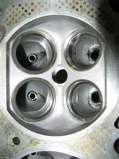
I’ll start with the clean up in a proprietary detergent I use for cleaning engines. This is the carbon-packed chamber and oil varnished head before the soak.
After a one-hour soak and some brushing with soft-bristle brushes, it comes out looking like this.
On to the important stuff. The RB26 has three major coolant outlets along the head on the intake side. A mild port clean-up will make the coolant flow a lot better and will trap air less. Here’s the small front water port that you don’t need to worry about. It only runs from a bypass behind the thermostat, and is closed off by the thermostat once the engine is at operating temperature.
Here’s one of the three ports. You can see how much of it is blocked by bad casting… All three ports look like this.
 |
| After scribing it to the size of the gasket. |
 |
| Looks a lot better after cutting. |
Next we’ll go into porting.
Now with video! Ahh, porting. What fun… Fortunately Nissan left us room for improvement. For engines generating power upwards of eight or nine hundred HP, there’s not a whole lot that needs to be done. However, the places that need attention will give the motor more power whether it’s stock or in clapped-out drag trim.
First item that needs attention is the big ‘ol hump in the exhaust port. If you’re using an exhaust manifold other than stock, it needs to go. In this pic you can see the offending hump. The other thing you see is that the gasket is considerably larger than the port. Same goes for the stock gasket. (See this Guide for Exhaust System Overhaul) for the Down-pipes and Cat-Back Exhaust Components. If you really wanted to, you could gasket match the port as long as the exhaust manifold is the same size. Resist temptation to make the port runner the size of the gasket. RB26 ports don’t need to be any larger than they are for all but the most extreme applications. You’ll lose power in the low and mid rpm for sure, and can hurt top-end power as well.
 |
| Here’s the port with the hump removed. |
When valve seats are installed, the throat is milled to remove any material overlap. While this is a good thing, it leaves the port “unfinished”. It leaves bad transitions and irregularities that create turbulence in the most critical part of the air stream. The goal is to make the transition through the turn and into the valve pocket as smooth as possible.
We take a similar approach to Solving the Twin Turbo Shuffle Problem.
In the following picture, you can see a small lip in the short-side radius. The short-side radius is where air is hanging on for dear life as it rounds the corner. Any disturbance here will cause the air to separate from the port floor and slam into the valve, rather than try to follow the port wall and exit around the valve. You can imagine how bad this is if you think about that air slamming into the valve and going all over the place, disturbing the rest of the air stream as it’s trying to enter the port. You can round this sharp lip, but under no circumstances should you remove material from the floor of the port. Lowering the floor makes the short-side radius even shorter. Big no-no.
Here you see the where the mill gets the outside radius of the port. Not as critical is the short-side, but needs to be smoothed, just the same.
Here’s what the bowl looks like when it’s been smoothed out. It’s hard to get a picture of the short-side radius. Just use your finger and you’ll feel when the lip is gone and it’s nice and smooth. This bowl could be considered finished, but I’ll hit it with a 120-180 grit cartridge roll later on. You do not polish ports. Polished ports leave nothing for a boundary layer to hold on to, and will hurt power. The stock ports are smooth enough from the factory that you’ll gain nothing by sanding the entire port with a cartridge roll, other than a pretty port that no one will ever see.
Another thing is to try as hard as you can to remove as little material as possible in the bowl. You do not want the port to be larger than the seat ring. The port should be expanding out as it gets to the valve seat. This makes air want to exit around the valve. If the port is larger than the seat and has to compress again to get through it, it focuses the air more towards the valve.
 |
| Other than cleaning up, this port is done. |
In the following three pictures, you can see the mill cut into the intake valve bowl. The third picture shows just how bad this transition really is, with a large lip.
 |
| Here is the port after cutting. |
And the port after it’s been smoothed with a 120-180 cartridge roll. Can you guess how important it is to stay off of the valve seat with the carbide cutter and sand paper? Coming up against it is OK as long as you stay away from the 45 degree seat cut where the valve seats.
The reason for three and five angle valve jobs is to make the air flow smoother as it makes the turn around the seat ring, and into the cylinder. It is possible to grind the valve seat with the carbide up to the 45 degree cut and obtain another 2mm or so of port opening. While this may sound good because it makes the port opening larger, you lose the third angle in the valve seat and outflow becomes very turbulent, making the port actually flow less. Don’t do it.
 |
| Here’s the four ports cut, but not yet smoothed. |
Once again, do not open the intake port larger than stock. Even with a 1mm larger valve, the only thing that should be opened is the bowl as it transitions outward toward the valve seat. If you open the port in the turn to the valve very much, the air will lose velocity and become sluggish right where it needs to be going fastest. Simple steady-state flow bench #’s don’t mean anything here; the air flow is anything but steady state and relies on velocity to fill the cylinders. Big ports will kill sub-10,000 rpm flow.
I made this short video for cutting the intake bowl to show how quick and easy it is. The key is going slow and easy. Once you remove material, you can’t put it back easily.
It’s been a while, and the engine is now almost complete. I’ll finish up the head in this post.
While most of this stuff (steps) is available in the FSM, it’s good to see the stuff in action with real photos and video. Please keep in mind that I skip lots of steps in this thread. To list and show every little thing would consume huge amounts of time to write up. I’ll try to get the important stuff in.
Not going to show the valve clean up. It’s really messy. I’ve found that the best way to clean the valves if you don’t have access to specialized cleaning detergents, etc., is with a drill press, some 240+ grit cloth, and WD40. Chucking the valves up in the press won’t hurt them at all, just do it lightly. Be careful to keep the paper off of the seat contact area, and don’t go any higher on the stem than the carbon. The valves are very hard, and you won’t be removing material with simple sandpaper any time soon… Hard carbon is almost impossible to remove from the valves by any other process than mechanically, like this.
Related: How to Clean your Engine Bay and Remove that Black Gunk.
Once the valves are clean and all the carbon is removed, the first thing to do is to check the guide play. The FSM gives the distance for the valves to be off the seat. The back and forth movement is checked with a dial gauge. Bucket-type lifted valves fare much better than rocker-type lifted valves. Rockers put a side load on the valve as it sweeps across the tip, opening and closing. Buckets take up the lateral load from the cam sweep.
 |
| Checking the valve guide clearance. |
Here I’m lapping the valves. This involves a special grinding compound that essentially mates the valve to the seat. There are different grits, but 99% of the time, only the finest grit will be needed. Over time small pits develop in the seat and valve contact area, which can cause valve leakage. Most of the time lapping will remove the pits and restore a perfect seal. I set a stopwatch and do each valve for 1’ 30”, taking the next 30” to change to the next valve. Total time for each valve is 2 minutes. This ensures I lap each valve the same amount of time. After 12 valves straight (just for the intake), your arms and wrists have had it. If the first round doesn’t remove all the pits, I do it one more time. If this still doesn’t work, I cut the seats and valves. Too much grinding can cup the contact area. The other thing lapping does is allow you to see if the valve and seat are contacting 360*. If the valve was a little bent, or the seat was damaged and sunk in one place, there would be no contact mark. You can also see the size of the contact ring, but that’s for another day…

Here you can see the gray ring on the intake and exhaust seat where the valve was making contact during grinding.
I did another short video to show you a couple of the lapping techniques.
Next the valve spring seats go in. Don’t forget them. Valve springs will grind into aluminum. Once all the seats are in, you can install the seals. A six-point, 10mm socket for the intake, and 11mm socket for the exhaust work well to install the seals. The size is just perfect for holding the seal without damaging the rubber, but small enough to push down on the steel collar. Dip them in oil, and push them onto the guide. You’ll feel them “pop” into place. This shouldn’t need to be said, but clean the sockets before you use them for this. For that matter, clean any tool you use for assembling an engine. It’s not a good practice to install head bolts with the same socket you just used to change the brakes without cleaning it first.
 |
| Here’s the spring seats and guide seals installed. |
Next you can slide all the valves in. Use a drop or two of oil and spin them in to lube the guide. The seals will now hold them in place so they won’t slide out.
Next I put all the springs and retainers in. Many valve springs have a top and bottom. Look at the coils. If it has tighter coils towards one end, that’s the bottom that goes towards the spring seat. I have a spring tool that allows me to install all the gear at once. Most will have to do one at a time.
I took the next two shots to show you the normal way of compressing the spring, and then installing the locks. The other tool I have lets me place all the locks on top of the retainer and just collapse it. The locks install automatically.
This shot shows the locks on. Dip them in oil so they’ll stick better. The frustration you’ll have here will help you understand why I have the other $350 compressor that installs the keepers automatically…
 |
| Here’s the finished product. |
Here’s where the shims go. Make sure the side that was against the valve is still against the valve. Sometimes it’ll be slightly dented (only by micrometer), and will change the gap. It’s just good practice to place things the way they were, even if they don’t need to be.
However, the first thing you’re going to do is measure all the shims. Even with “pon” cams, chances are you’ll be changing a few, and it’s better to know what the beginning thickness is. Some cams you’ll be changing all 24. This shim is 2.99mm
 |
| Here’s the new Tomei 260 compared to a stock cam. Big difference. |
Place the cam in a “neutral” position where it’s close to where it would be at #1 TDC. “Neutral” means not just lifting one set of valves to max lift, but putting even pressure on at least two sets of valves. Then tighten the caps evenly, and DO NOT BEND THE CAM. It needs to drop into the front thrust area evenly and straight down.
 |
| Once all the caps are down, torque them appropriately. |
I lay all the thickness gauges I’m going to use out, so I’m not constantly looking for the one I need in the pack.
Checking the clearance. It’s tricky with the RB26. Too much clearance, add shim in the amount it’s out. Not enough, take shim away in the amount it’s tight. Simple. Bad thing is you need to take the cams back out to change them. Before checking anything, turn the cam at least twice to make sure everything is seated. The head needs to be propped up front and rear because the valves will protrude past the deck.
On the final cap installation, you need to add some sealant to the front of this cap. Very sparingly. There is a small passage in there from the rear of the seal to the inside of the head. If you block it, oil pushing out of the front journal to behind the seal won’t have anywhere to go and will blow out the seal. Not fun to take it all back apart and clean it up. Wipe off the excess or it will cause the cover gasket to leak.
 |
| All done. |
Like I said, I skipped some steps. Installing the lifters, make sure they spin freely once installed. They turn while in action, and if they’re tight, it’ll burn up a lifter and cam lobe. The baffle plates only go on one way. Installed any other way, the covers won’t go on. They're on in the pics, but need to be off for timing the cams, which I'll cover later.
Dirt is the enemy. Compressed air is your ally. Be as clean as you can and try to use lint-free rags for touching the motor. Cheap paper towels work well. Shop rags do not. I know my blue bench top looks dirty in these pictures, but I assure you it's sterile (literally) before I start. All the discoloration is from years of burn marks from welding. At over US$40,000 for 500 square feet (just for the property, not the structure) I don't have a clean room yet.
On valve lapping: Someone asked me, why not just cut the valves and seats? The main answer is because there's nothing wrong with the valves and seats that are in this motor. If it requires more than about 2 minutes of lapping with a fine compound, I'll usually cut them. Cutting is not so simple in a high performance application. You also need to cut the other two angles in the seat to adjust the placement and contact size on the valve. Then you need to completely reshim everything. The above "pon" cam installation required changing three shims vs. 24.
We’re in the home stretch now. I’m going to skip over the stuff like measuring the rod bearing and piston pin clearances because it’s the same as we did back with the main bearings. Same goes for the piston clearance. Measure the bore, measure the piston or pin, the difference is the clearance.
With the new rings from Arias in hand, we can set the end gaps. Generally accepted ROT (rule of thumb) is .004” (.1mm) per inch of bore is the minimum gap. This bore is 3.464” (yea, that's 88mm), so the minimum gap would be .014” or .35mm. It’s not always good to use the minimum gap. Engines that have high thermal loading like forced induction, nitrous oxide, etc., should use more gap. If you were running a fuel like alcohol, you could close up the gap a little. Don’t worry if you accidentally grind a little too much and make the gap too big. You could effectively double the gap and not see a decrease in performance. It’ll affect a leak down test, etc., Click here to see How to Check Engine Compression. but won’t really hurt performance, especially in the rpm range where you’re making power. I’ve seen engines with broken rings that you couldn’t even tell something was wrong until they were torn apart. Basically, don’t get too hung up on ring gap. Too much=OK. Too little=Very Bad.
On ring expander tools: I hate them.
First, if you have a deft hand, it stretches/tweaks the ring a lot less when it’s twisted on by hand. A ring expander that stretches the ring out enough to completely clear the piston is scary business. I used one once and threw it away. If the ring binds up, just stop and back up. People break rings when installing them in a hurry and using the armstrong method. In 25 years of assembling engines I’ve broken exactly one ring, and that was about 25 years ago. Second, every pro engine builder I know, including the heavy-hitter mainstream guys, installs the rings by hand.
 |
| Checking the gap .016”. |
 |
| Soldiers, ready for battle. Once again, don't bust my chops about the "dirty" bench. It ain't dirty! |
 |
| An army of one. Arias pistons and Carrillo rods. |
 |
| The Carrillo SPS bolt. The best and strongest rod bolts money can buy. |
These rod bolts torque to 65 lbs. Normally I use a stretch gauge, but it’s impossible to get in there, so for the RB it gets torqued.
 |
| All masked up and ready for paint. |
Here’s the almost complete short block. Pistons in, studs in, gasket on. Check that shiny new paint job.
A few words on studs: Studs are not necessarily stronger than bolts. The main advantage to a stud is that they use a fine thread at the nut end vs. the course thread in the block. This makes for smoother torquing, and allows you to take the fastener closer to the yield point safely. For instance, say a fastener has a yield strength of 200,000 psi. With a course thread, tightening can be erratic from one fastener to the next, so the manufacturer may set the tightening torque to achieve 60% of the fasteners yield to ensure it never goes over. A fine thread like those from ARP is set at 75% of the fasteners yield. That’s 120,000 psi vs. 150,000 psi of clamp force.
Related:
If you ever break a stud, here's a Trick to Remove and Fix Broken Studs.
You never tighten a stud in the block more than hand-tight, or just barely snug. There should be zero upward pulling or pushing of the block threads before the top nut is tightened. If a stud like those from Tomei, with an extension to bottom in the bolt bore, is tightened into the block, it pushes up on the area of the block around the stud, creating a high spot. These high spots guarantee that the seal around the cylinder is a weak one. There’s nothing wrong with the fastener, per say, but in the wrong hands… The ARP studs have a shoulder machined above the threads as a positive stop. If you were to tighten it, it would only clamp the threads together, but would still pre-stress the block in the area around the fastener. Don’t do it.
It’s much easier to lube the threads before the head is on. Lube 100% of the threads. Do not lube the threads in the block. You don’t want those turning. If you use a threadlocker or sealer with studs (only in the block), it needs to be tightened within an hour, or so, before the locker sets up.
SR20 studs can not be pre-installed like this. The head can’t slip down on the studs and clear the chain guide.
Where the power is made. This is a touge engine. The quench (squish) pads stay in place. Much better mid-range power with the pads. This head is pristine. Perfectly flat, with no imperfections, so it’s not getting cut. It’s a waste to machine things that don’t need it. My thought is that you’re taking away rebuild-ability.
 |
| The head installed. |
 |
| Another shot. |
Here's where people are going to bust my chops...
It's info I've been sitting on for about a decade and a half. Well, the cat's out of the bag. I know I've said I never did an extra "oil return" on an RB26, and that's true. But I never said (I don't think) I never added anything for crankcase ventilation to aid oil return through the stock pasages. Semantics...
Why do I discourage people from doing this mod? BECAUSE YOU DON'T NEED IT! And, if it's done wrong, you'll end up with more problems than you've solved. Originally, this engine turned around 11,000 rpm, boosted way over 30 pounds, and made hp north of the millennium mark. The new configuration doesn't need it, but because the mod is already done to the pan, the parts are there, etc, it's going on this engine.
The following three pictures are of the additional crankcase vent. I first started doing this mod on the 26 in the mid 90’s. It’s a common mod for high rpm engines, so it was a no-brainer for the RB26. Soon thereafter, the Internet got a hold of it and speculation as to its function ran rampant. “Additional oil drain-back” became the consensus, and consensus became fact. Now it’s well known as the additional oil drain back mod… Then it became a fact that all the oil in the engine will pool in the head and the engine will blow if you don’t have it done…
Really? Let’s examine some facts. The RB26 has been lapping the Nurburgring starting years before the R32 came out in 1989. Lap after lap at full-boogie. Since then, the R33 and R34 have been lapping the same track. The N1 GT-R that races in the N1 class doesn’t have this mod done. Super Taikyu RB26’s don’t have this mod done. I can assure you that the RB26 does not have an oil drain back problem that warrants modification to implement an additional one.
On Youtube you can find some videos of the Porsche Turbo engines in a cradle that simulate a run of the Nurburgring to test the oil system. Nissan has the same thing.
So what’s the deal??
Windage and blow-bye in ultra-performance engines. You get an RB26 up in the 10,000rpm neighborhood and lean on it with 2+ kg of boost and you have a nightmare.
See, all but one of the oil drains back into the sump on the RB26 are on the left side of the block. When we examine crank windage, that’s the side of the engine where the crank counterweights, rods, etc., are moving in a downward direction, essentially “pulling” oil back down out of the head. In the right-rear of the engine, there’s another port. This port is on the “pressure” side of the motor, and windage blows up this passage, creating an actual suction on the drain-side of the motor.
At high-rpm, high-boost, windage and blow-bye gasses can be so severe, that the single port on the right side isn’t adequate. Gasses are moving up all the ports, sometimes at high velocity. This effectively keeps oil from returning to the sump. What the large hose from the sump to the back of the head does is give the blow-bye gasses another path to the head, and allow the oil to return down the normal returns along the left side of the motor. It needs to be above the oil level in the sump, but below the baffle.
In a drag motor, if we accelerate forward at 1g, the oil in the sump will stand up at 45 degrees. It’d be neat to hear an explanation of how the oil in the head overcomes the laws of physics and somehow runs forward to the front of the engine. In a circuit/touge motor like this one, oil will indeed return down the hose to the sump because not all of the acceleration is forward. This is the reason it needs to be lower than the baffles in the pan; on that side of the engine, any oil returning will simply be picked up by the crank and added to the hurricane in the crankcase.


What we found was that under these extreme conditions, we were pumping a quart of oil out of the breathers and into the overflow in a 400m pass. Not only was it not returning, but the blow-by gases were pushing it out of the engine. Additional vent was added, and the problem disappeared. It needs to be said that in engines turning 9,000 rpm and boosting 1.7 bar, engines making north of 750hp, this "problem" has never presented itself. That, and the problems you can create if it's not done properly are the reason I've been so against it in more reasonable engines. An example is if you put the tube below the oil level in the pan, not only are you choking any venting action, you're giving the oil another place to go during acceleration. Like I said above, oil will leave the sump through the hose.
Hate away.
On 88mm. There's talk on the Internet that it weakens the cylinders too much... I don't know what others have experienced, but I've never had a problem. This engine made BIG power for a long time and had two failures. Dropped a valve both times. I don't recommend going all the way out the first time. I leave the bore stock with a new hone, if I can. Then it's up to 86.5mm, and so on. "Rebuildability" (is that a word?).
For the rest of the external parts on the engine, you can follow this guide: How to: RB26 External Engine overhaul


Comments
The other thing often overlooked is crankshaft harmonics breaking the oil pump from torsional vibration at the crankshaft snout/oil pump drive interface. Remember that a good balancer must have sufficient weight (no alloy 'pulleys' EVER) to absorb and disipate these destructive vibrations.
And crankshaft endfloat?
Thabks
I've also noticed how bad the lip is in the bowl from the mill. I couldn't believe it on the first head, but the other 2 i had varied from almost smooth, to a 1.7mm lip! really easy fix as you pointed out, and I'll be doing it soon. Thanks again for the writeup! :) -Dave
Post a Comment